SL-SeriesSL-A2300/ SL-A2600/ SL-A2101/ SL-B2300/ SL-B2600/ SL-B2101
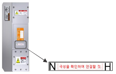
SL Series is divided into Hot/Neutral for all single phase I/O,
voltage of the input line shall be separated and installed accurately.
※ HOT Line : Voltage similar to input voltage measured by frame ground (FG)
※ Neutral Line : Voltage measured within 10 volts relative to frame ground (FG)
Check & connect polarity
SE-SeriesSE-A2300/ SE-A2600/ SE-A2101
SM-SeriesSM-A2300/ SM-A2600/ SM-A2101
SS-SeriesSS-A2300/ SS-A2600/ SS-A2101/ SS-B2300/ SS-B2600/ SS-B2101
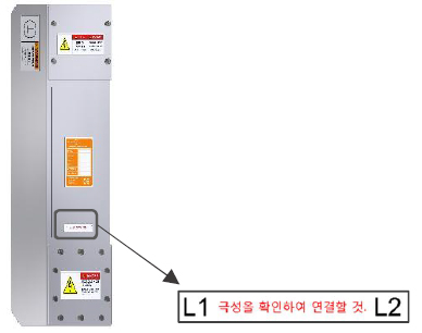
SE/ SM/SS series has single-phase input and output divided into L1 and L2.
It does not distinguish between L1 and L2 by voltage,
Input and output lines L1 and L2 must be connected properly.
※If the inputs are connected in the order of L1 and L2, the output must be connected to L1 L2 in the same order
Check & connect polarity
SD-SeriesSD-A2300/ SD-A2600 / SD-A2101/ SD-A2201
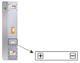
SD series is divided into + and - and connects input lines.
If the input is +, the output must be connected to +, and if the input is -, the input and output must be connected to -.
When the input is three lines, since one line is FG, it may be connected to the input unit FG connector.
(It is a bolt-shaped ground connector on the wall of the casing)
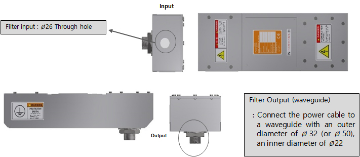
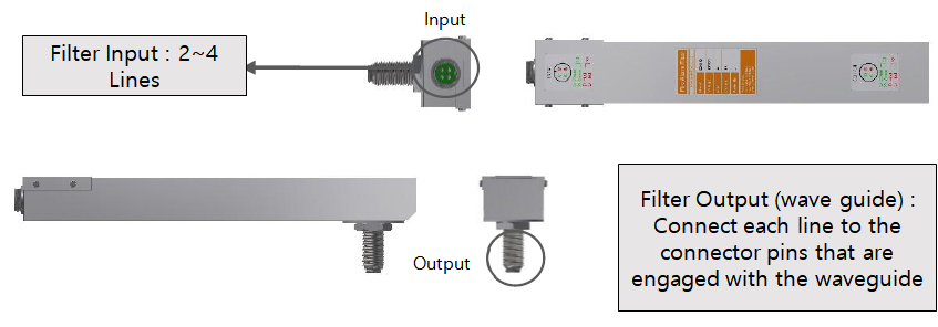
Installation Image (Powerline Filter)
1) I/O
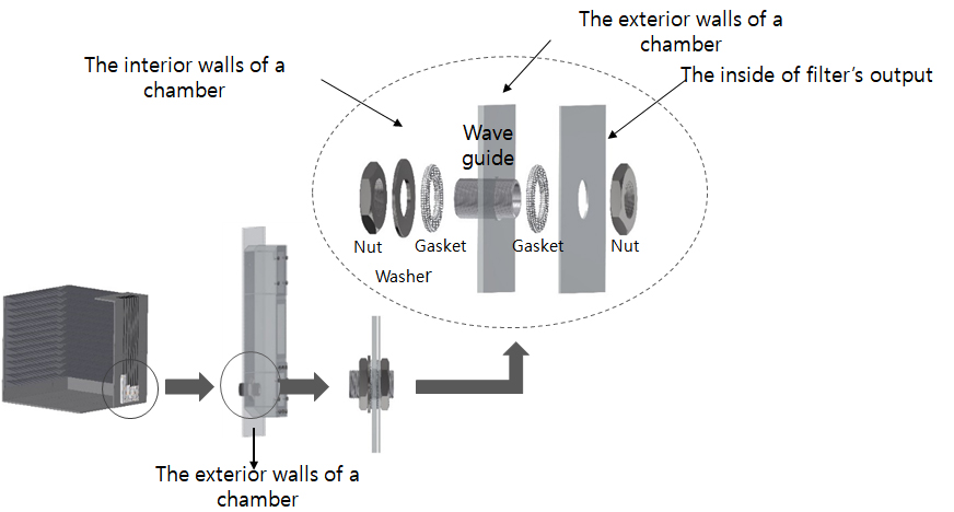
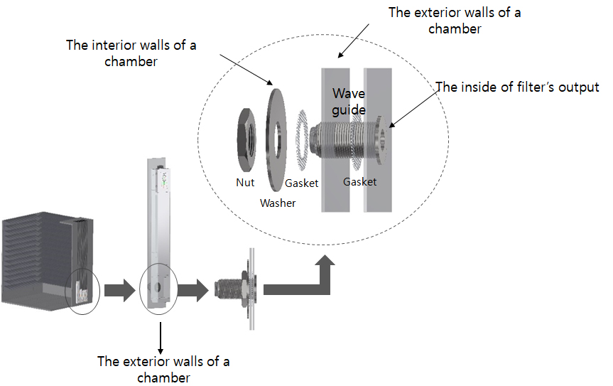
2) Image of output wall mount
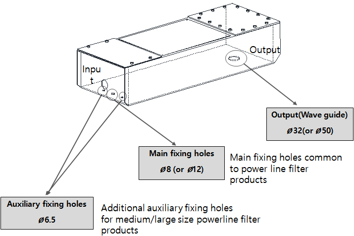
3) Filter fixing hole size reference image
SL-SeriesSL-A4300/ SL-A4600/ SL-A4101/ SL-B4300/ SL-B4600/ SL-B4101
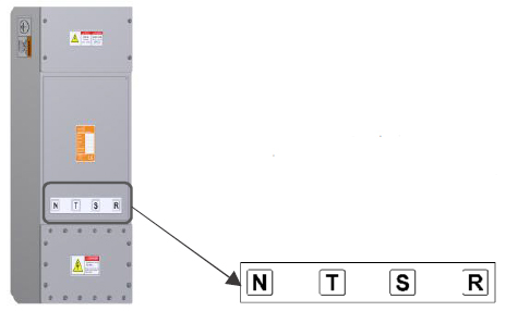
All three-phase I/O are divided into R/S/T/N phases and must be installed for each line.
The low leakage filter has a circuit based on the N phase
The N phase of the filter and the N phase of the input power must be matched.
The R/S/T phase is irrelevant even if the order is changed.
※ N-phase: Lowest voltage within 10V of ground among four wires
※ If there is no separate N phase, it can be used in connection with an external F/G
SE-SeriesSE-A4300/ SE-A4600/ SE-A4101
SM-SeriesSM-A4300/ SM-A4600/ SM-A4101
SS-SeriesSS-A4300/ SS-A4600/ SS-A4101/ SS-B4300/ SS-B4600/ SS-B4101
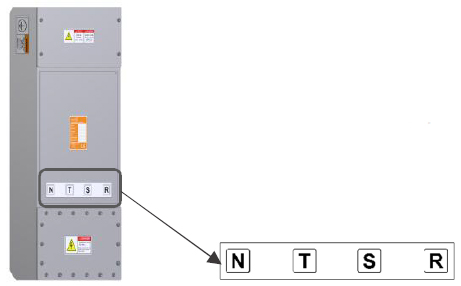
The three phases of the SE/SM/SS series are divided into R/S/T/N phases
You can install it according to each line.
Note that, like the SL series, R/S/T phases are irrelevant even if the order is changed
The N phase of the filter and the N phase of the input power must be matched.
Installation Image (Powerline Filter)
1) I/O
2) Image of output wall mount
3) Filter fixing hole size reference image